KswapMR2.com
SW20 Chassis Harness rework for stand alone harness use.
Pics and descriptions by Eric Hux of Hux Racing,LLC
You can also see a real time video of this process by clicking the link
SW20 Chassis Harness Rework Video
The plan here is to detail what is necessary to prep the chassis side of the SW20 harness for stand alone engine harness use. Removal of all the unused bits is a huge necessity and makes future upgrades and troubleshooting possible. Much of this is similar to the services I used to offer, but tweaked a bit to make it more DIY friendly. What some sell as "plug and play" for the SW20 is simply laughable, and as such, I have put together this "How To". I have invested untold hours in helping people unfuck wire work they paid good money for. I will explain many details that have tripped up the uninformed. Please note, engine choice really does not matter as nothing performed here is powertrain specific. Please read through the entire tutorial before attempting, as steps performed in the beginning might not make sense unless viewed in it's entirety.
Things to Note:
1.Chassis harness is being setup for relay bank and ecu to be installed behind the seats. Why you ask? Because trunk install of any of this makes little sense unless you would like 6-8ft of extra wiring and alt cable. Plus, now your electronics are in a waterproof area if you plan to cut into the trunk.
2. You will need to add a relay bank, or pdm, for the power supplies. We will address that in a separate write up.
3. The main power feed to rear of car is only rated at 40amps. All large fuel pumps, fans, etc, should have relays powered by battery through a relay.
4. Do not power anything from the alternator cable. I repeat, do not use the alternator cable as a power feed.
5. The harness is built this way with the intention of tucking the tail light run, down the inner sheet metal on left side of car.
1. This is where we start, Shown is a 91-92 NA harness. All sw20 harness will be similar, auto as well. If you have a 99' sw20, Congrats....lots of changes will be found there. A 93+ will have a speed signal wire to dash. All this will be addressed in the stages.

2. First scary step coming up. We need to chop the factory fuse box off as shown plus the ecu connectors and EA1 plug. The large wire pair here is the alternator lead to front of car. You can see the other connectors I eliminated. Do not cut ABS connector if keeping ABS. (2 wire shielded pair/ grey connector)


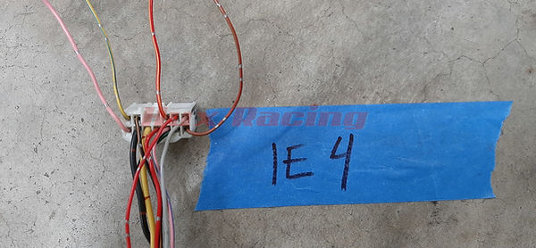
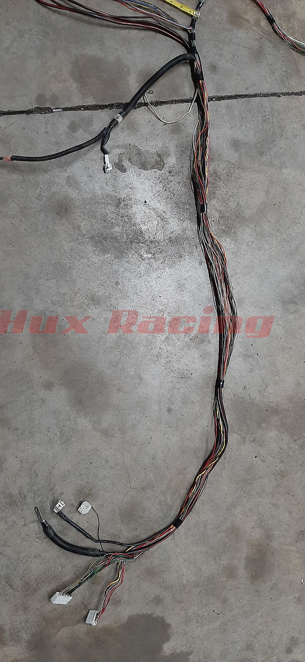
3. Now we need to strip off the factory harness sleeving and cut off the grommets. Copy as I have done in the pics. Please note the blue tape with arrow denoting only to strip from this point forward to the main connectors. Do not strip the leads heading to the defrost and 3rd brake light (can be clearly seen untouched in middle of harness run) . Do not cut off the rear/left ABS connector if keeping ABS. Use zipties to keep the harness bundled together, the locations I use can be seen in the pics. You will find that as you unloom the ecu area that many loose wires will fall away, this is expected. The engine compartment temp sensor wires are one example of wires that will disappear. If the blue/black fuel pump wire/ connector becomes loose , be sure to hold onto it. You can see I cut off all connectors near ecu and factory fuse box.


4. This is the connector designations for the SW20 kickpanel. Large one at bottom with 2 bolt holes is the alternator cable. Single wire connector is the 40amp main feed. You might want to print the connector diagrams.

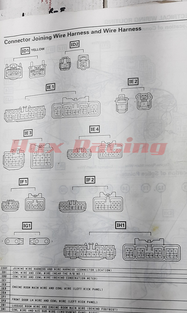
5. Lets clean up connector IE3 first since it has the most unused wires. What do they go to you ask. Don't know, don't care, you wont need them. There is typically only 1 wire left if not running ABS. If runnning ABS you will have 4 wires left. Follow the pics.

6.. Without ABS this black/yellow wire will be the only wire left in this connector. It runs to the power antennae plug. If you have no power antennae you can delete it as well.

7. The only wire remaining in this connector for this build. No ABS

8. If you are keeping abs you will have these wires remaining. 93+ cars will have different color ABS wiring ( a black,red, and white/black), same pin locations.

9. This is how to depin these connectors. 1st pry up the pin lock. 2nd you need to unlock the pin, can be done with a paper clip but I prefer a sharp pic. When pulling each of the unused wires they should be loose and not connected to anything on the other end.


10. This is your fuel pump wire. Mating connector is on firewall behind left seat. Hold onto this lead. In a 91-92 there is usually only one wire here. The 93+ will usually have some unused factory security wires here. Automatic will have many more. All we care about is the blue wire with black stripe.

11. We are now going to cut the alternator cables and main feed to length. I like to use 24" but your swap may vary. Use the defroster/3rd brake light wires as a land mark as to where to run from main harness.


12. Seperate all remaining loose wires as shown in the pic

13. towards the tail light section you will have numerous splices and a red/black wire. The red/black is the reverse lights, save this wire. You can trim all other pigtails and wires running loose from the tail light section.

14. Loose wires trimmed and reverse light wire remaining.

15. This is the A.C compressor wire if you are keeping A.C. . Otherwise pull forward and delete. Black with White stripe.

16. We need to find out which black wire is the tach. Black wire with single dot tracer is the tach wire, we are saving this one. In the Lower image I am holding up the wire that is NOT the tach. . Remove the wire displayed in lower image. I am holding the IE1 connector.


17. This image shows the remaining loose wires that we will be keeping . These run out at center of harness. Keep reading directions for clearer location.
black/white a.c. clutch
yellow/green factory temp gauge in dash
red starter signal
black/orange ignition on signal from key switch
Black tach
green/white c.e.l. light
white/black temp sensor ground and start relay trigger ground
yellow alternator light
yellow/black oil pressure light on factory dash

18. Some typical wires for deletion. ( the loose ones pulled away from connectors below) We will depin anything left loose. I like to save that red/yellow to extend the reverse light wire. Yes the 3 loose wires on IE1 are going to be removed.

19. Lets extend that reverse light lead forward now. Details in the pics.


20. After extending reverse you can bundle the wires as shown with electrical tape.

21. Now find these 2 white/black wires by middle of harness run. You can use the ground wire with ring terminal as a land mark.

22. Cut the grounds as shown.

23. Orient the cut wires like this now.

24. Your connection should look like this.

25. Now we bring all these small wires together as shown. Adding the fuel pump lead back in. Run the reverse light lead into the bundle as well. don't forget the white/black ground wire from last steps.

26. Here I trimmed all those wires to 18". You can see how i cleanly taped the harness together to organize the bundles. All the unused junk is now gone.

27. We need to terminate all these ends with connectors now. I will be selling kits with all the crimps, pins, connectors, labels, etc. for you to do this. The pics are self explanatory in this section.


28. Lets pin this male molex connector next. You can use whatever connector you want but these things work great. I like to pin as follows: I recommend doing the same if you want future help from others. (male connector uses female pins)
1 .black---- tach
2. blue/black--- fuel pump
3. black/orange-- ignition on
4. red/yellow (whatever you extend the red/black with)--reverse lights
5. green/white---cel
6. red---starter signal
7. white/black---- starter relay ground and temp sensor ground
8. yellow----alternator light
9. yellow/black----oil pressure light
10. Purple----speed on 93+
11. yellow/green----water temp stock dash
12. black/white ----a.c. compressor clutch

29. This is the male molex connector. The black mark denotes pin1. The other pins are as follows, looking at rear of connector(rear shown in pics). It is labeled on connector also but really small.
3 2 1
6 5 4
9 8 7
12 11 10

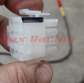
30. Pins 3,2,and 1 populated.

31. All wires terminated with connectors. Plug and Play right!!!

32. Another view of teminated sections and taping to prep for loom.

33. Cover the tail section in 1/2" corrugated loom and the main run in 3/4" loom. Our work here is done on this section. All the shit has been removed and you are 1 step closer to a proper harness.

34. This is 3lbs 13oz of crap removed from that chassis harness.

Congrats, If you made it this far. I have done so many of these that I take many of the simplest steps for granted. I hope I have made it clear enough for you to duplicate. Thanks for any feedback.